Detailed Explanation of Transformer Voltage Conversion: Core Mechanism for Voltage Step-Up and Step-Down
Transformers are essential components in modern power systems and electronic devices, enabling efficient voltage conversion through the principle of electromagnetic induction. From high-voltage transmission lines to everyday phone chargers, transformers play a critical role in ensuring stable power supply across numerous applications. This article provides an in-depth explanation of how transformers convert voltage, including their operating principles, core components, and common application scenarios.
Basic Structure and Key Components of a Transformer
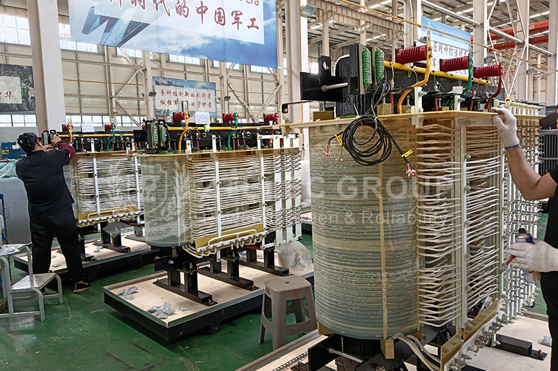
A transformer typically consists of three main components:
Primary Coil (Primary Winding): Receives the input voltage and generates an alternating magnetic field.
Secondary Coil (Secondary Winding): Outputs the converted voltage induced by the magnetic field.
Core: Generally made from silicon steel sheets with high magnetic permeability to enhance magnetic coupling and reduce losses.
When alternating current flows through the primary coil, an AC magnetic field is formed in the core. This field induces a voltage in the secondary coil, enabling energy transfer without direct electrical connection.
Core Working Mechanism: Electromagnetic Induction
The operation of transformers is based on Faraday’s law of electromagnetic induction. When alternating current passes through the primary winding, it produces a changing magnetic flux. This flux induces an electromotive force (EMF) in the secondary winding according to:
E = N × ΔΦ / Δt
Where E is the induced voltage, N is the number of coil turns, and Φ is the magnetic flux. The alternating nature of the magnetic field makes voltage conversion possible.
Voltage Conversion and Coil Turns Ratio
The voltage output of a transformer depends on the ratio of the number of turns between the primary and secondary coils. The relationship is expressed as:
Vp / Vs = Np / Ns
If the secondary coil has more turns than the primary coil, it steps up the voltage. Conversely, fewer secondary turns result in voltage step-down. For instance, if the primary has 400 turns and the secondary 600 turns, applying 40 V AC to the primary produces about 60 V at the secondary.
In real-world applications, slight voltage drops may occur due to copper and core losses, but these do not significantly affect reliability.
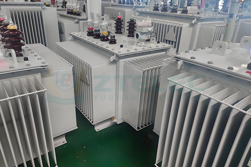
Step-Up and Step-Down Transformers
Transformers are categorized according to their function:
Step-Up Transformers: Increase voltage, commonly used in power transmission to reduce energy loss over long distances.
Step-Down Transformers: Reduce voltage for household, commercial, and industrial use.
Isolation Transformers: Use equal coil turns and provide electrical isolation to prevent interference and enhance safety.
The Role of the Transformer Core
The magnetic core is a crucial component that significantly affects transformer performance. Its key functions include:
Enhancing magnetic coupling: High-permeability materials improve energy transfer efficiency.
Reducing magnetic reluctance: Ensures smooth magnetic flux flow.
Minimizing losses: Laminated silicon steel reduces eddy current and hysteresis losses.
Common Applications of Transformers
Transformers serve a wide range of industries and application scenarios, including:
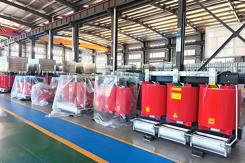
Power Transformers: Boost or reduce voltage levels within power grids.
Control Transformers: Provide stable low-voltage power for industrial control systems.
Rectifier Transformers: Used with rectifier circuits to convert AC to DC for chargers and adapters.
Current Transformers: Used for measurement and protection in power systems.
Isolation Transformers: Prevent interference and ensure operator safety.
Practical Usage Precautions
Load Matching: Operating beyond rated load may cause overheating or voltage drops.
Frequency Compatibility: Transformers must match the power system frequency (50/60Hz) for optimal performance.
Thermal Management: Proper cooling and ventilation are necessary to avoid thermal damage.
Frequently Asked Questions (FAQ)
Q1: Can a transformer operate using DC power?
A1: No. DC does not produce a changing magnetic field, so no voltage is induced in the secondary coil.
Q2: How is the turns ratio selected?
A2: It is calculated based on the desired input and output voltage. For example, reducing 220 V to 12 V requires roughly an 18:1 ratio.
Q3: Does a transformer consume power under no-load conditions?
A3: Yes. Even without load, transformers generate iron losses and a small amount of copper losses.
Understanding the mechanism of voltage conversion helps users make informed decisions regarding transformer selection, application, and maintenance. As key devices in power transmission and electronic equipment, transformers contribute significantly to modern energy systems and technological development.
- more+releated article
- 2026-01-04Common Power Transformer Faults: Causes, Solut
- 2025-12-312026 New Year Holiday Notice
- 2025-12-31Operation, Maintenance, and Service Life Manag
- 2025-12-30How to Select a 100 kVA–500 kVA Distribution
- 2025-12-29The Impact of NHN NMN Composite Insulation on
- 2025-12-26Practical Application of GPO-3 Insulation Boar
- 2025-12-2510kV Transformer Replacement Timeline: Install
- 2025-12-25Low Smoke EN45545 GPO3 UPGM203 Laminated Board
- 2025-12-24Merry Christmas — ZTelecgroup Christmas Cele
- 2025-12-24How to Select a Suitable 50kVA–500kVA Distri

