Application of K Factor Transformer
Analysis of Filtering Ability and Harmonic Tolerance of Isolation Transformer
1. Classification of isolation transformers
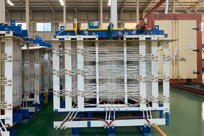
1.1. Classification according to input and output wiring methods: Usually, isolation transformers can be classified according to different output and input wiring methods: Dyn, Dd, Ynyn, YNd, Dzn, ZNd, Ynzn, Znyn eight categories, D or d means delta connection, Y or y Represents star connection, Z or z represents zigzag connection (English representation: Zig/Zag connection), uppercase indicates input, lowercase indicates output, N or n indicates neutral point, usually isolation transformer, especially UPS system and data room transformer wiring The main methods are: Dyn11 and Dzn0.
1.2. Classified according to the number of outputs: single output, double output, multi-output, etc. Usually, isolation transformers, especially UPS system and data room transformers are single-output transformers, and twelve-pulse rectifier transformers or filter transformers are dual-output transformers. The wiring method is Dyn11d0, that is to say, the output has two sets of independent isolated outputs, one set of wiring is Dyn11, the other set is Dd0, and the phase difference between the two sets of outputs is 30 degrees. For dual-output or multi-output transformers, practical application It is necessary to ensure that the loads of each group are as equal as possible, otherwise the filtering effect will be greatly reduced, but it is very difficult to ensure that the output loads of each group are equal in actual operation. For this reason, multiple output isolation transformers are rarely used in practice.
2. The meaning of K coefficient:
2.1, K factor is a conversion factor of harmonic heat loss, usually from 1 to 50, often used: 1, 4, 7, 9, 11, 13, 20, 30, the most often used are: 1, 4, 13 , 20.
2.2. Implications for power supply and power consumption network:
The K coefficient represents the severity of the harmonics in the power supply and power consumption network. The higher the K coefficient, the worse the harmonics in the power supply and power consumption network. K=1 means that there are no harmonics in the power supply and power consumption network, all of which are The fundamental component, the power supply and power network of the UPS system and the data center are: 13 and 20, and the K factor does not change with the load rate, but is only related to the harmonic spectrum of the network.
2.3. For the meaning of power consumption, power supply and power transmission equipment: K coefficient represents the ability of the equipment to withstand harmonics. The higher the K coefficient, the stronger the ability of the equipment to withstand harmonics. K=1 means that the equipment is not designed to withstand any harmonics. The ability of the additional heat loss of the wave can only be operated safely in the fundamental wave condition, and the ability of the equipment to withstand harmonics decreases with the increase of the load rate. Therefore, when the capacity of the power supply network is not limited, a larger capacity can be selected. For equipment, the ability to withstand harmonics of the K factor can be improved to a limited extent by reducing the load rate, but this is only one aspect. Many manufacturers and users mistakenly think that it is only necessary to increase the capacity. This is a kind of tolerance to harmonics of the K factor. One-sided understanding of ability.
3. The purpose of referencing the K factor to the transformer:
Usually, the K factor can be quoted in any power supply, power consumption, power transmission network and equipment, so for different types of transformers, transformers with different temperature levels, and transformers with different insulation levels can be added for reference, the purpose is to To improve the reliability of transformers, of course, different types of transformers, transformers with different temperature levels, and transformers with different insulation levels have different harmonic tolerance capabilities in the same harmonic work, and finally determine whether the transformer has a suitable anti-corrosion The harmonic capability depends on the average temperature rise of the transformer operating under the design harmonic conditions and the highest temperature point inside the transformer. If the same harmonic tolerance capability is to be achieved under the same harmonic conditions, the difference between design and manufacturing costs It is also very large. For dry-type transformers, some temperature, insulation grades (such as below 130 degrees and B-class insulation grades) and transformers made of some materials (low-density insulating wire-wrapped wire) are not able to withstand the K factor. Reach 7 or more, therefore, UPS system and data room transformers cannot choose the above transformers.
- more+releated article
- 2026-01-04Common Power Transformer Faults: Causes, Solut
- 2025-12-312026 New Year Holiday Notice
- 2025-12-31Operation, Maintenance, and Service Life Manag
- 2025-12-30How to Select a 100 kVA–500 kVA Distribution
- 2025-12-29The Impact of NHN NMN Composite Insulation on
- 2025-12-26Practical Application of GPO-3 Insulation Boar
- 2025-12-2510kV Transformer Replacement Timeline: Install
- 2025-12-25Low Smoke EN45545 GPO3 UPGM203 Laminated Board
- 2025-12-24Merry Christmas — ZTelecgroup Christmas Cele
- 2025-12-24How to Select a Suitable 50kVA–500kVA Distri

