Transformer Voltage Conversion: Principle and Implementation
The transformer is a static electrical device that enables alternating current (AC) voltage conversion without changing frequency. It operates on the principle of electromagnetic induction, as described by Faraday's Law: a changing magnetic field induces an electromotive force (EMF) in a conductor. This principle makes transformers a fundamental component of modern power systems.
1. Transformer Core Structure and Basic Principles
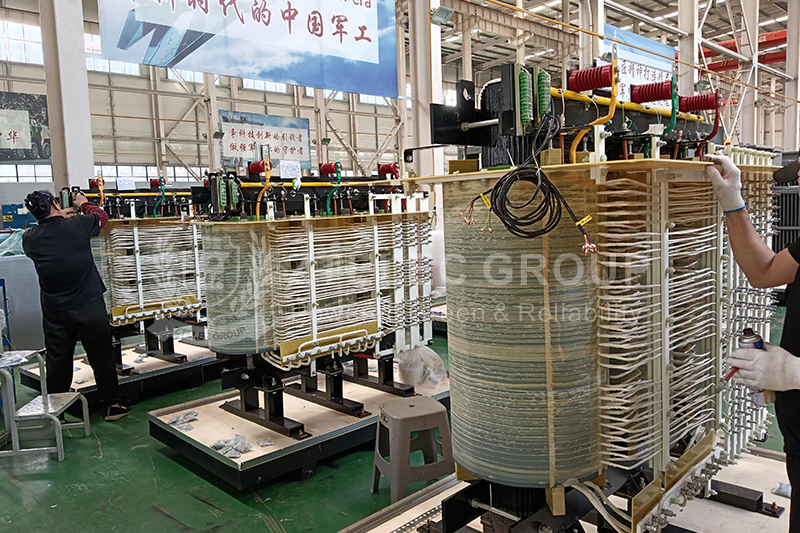
The core structure of a transformer includes the iron core and windings. The core, typically made from high-permeability silicon steel laminations, forms a low-resistance magnetic circuit and minimizes eddy current losses. The windings are divided into primary and secondary coils.
When AC flows through the primary winding, it generates an alternating magnetic flux in the core. This flux links to the secondary winding, inducing a voltage and transferring energy.
The voltage ratio between the windings is directly proportional to the turns ratio. The primary power and secondary power are equal under ideal conditions, as per energy conservation. The current on the high-voltage side is lower, while the current on the low-voltage side is higher, following the inverse relationship with the turns ratio.
2. Multi-Dimensional Analysis of Voltage Conversion
From an electromagnetic perspective, the changing magnetic flux generated by the AC in the primary winding induces voltage in the secondary winding. The rate of flux change determines the magnitude of the induced voltage.
From the viewpoint of magnetomotive force (MMF) balance, the MMF generated by the primary winding is largely countered by the opposing MMF of the secondary winding. This results in a small no-load current and ensures efficient magnetic coupling.
From the energy transfer perspective, the transformer functions through a sequence of conversions: electrical energy in the primary becomes magnetic energy in the core, and then transforms into electrical energy in the secondary. Since there is no mechanical movement, transformers offer high efficiency and long service life. The use of high-permeability cores helps confine the magnetic flux within a closed loop, enhancing performance.
3. Key Factors Affecting Voltage Conversion Performance
Several factors influence the efficiency, stability, and longevity of transformer voltage conversion:
Core material: High-grade silicon steel sheets and amorphous alloys help reduce no-load and iron losses.
Core lamination: Proper insulation and tight stacking of the laminations reduce eddy current losses and improve performance.
Winding design: Copper conductors offer excellent conductivity but are expensive, while aluminum is more affordable and lighter, though it requires a larger cross-section. Good insulation between layers and turns is critical to prevent short circuits and partial discharges.
Cooling method: Small transformers typically use air self-cooling. Medium-sized models often adopt oil-immersed self-cooling. Large-capacity transformers may rely on forced oil circulation, air cooling, or water cooling systems, depending on load demands and thermal management requirements.
Insulation system: Oil-immersed transformers use insulating oil and solid insulation like pressboard. Dry-type transformers use materials such as epoxy resin. The insulation system must endure aging and withstand transient overvoltages to ensure long-term safe operation.
4. Application Fields of Transformer Voltage Conversion
Power Systems
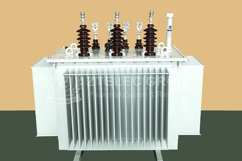
Transformers play a critical role in power generation and distribution. Step-up transformers are used at power plants to raise voltage levels for long-distance transmission, minimizing energy loss. At the distribution end, step-down transformers reduce voltage to safe, usable levels for homes and industries. These power transformers demand high reliability, efficiency, and large capacity handling.
Industrial Applications
In industrial settings, transformers serve a wide range of specialized uses, such as electric furnace transformers, rectifier transformers, and welding transformers. These units often endure extreme conditions, high currents, and harmonics. Their design must consider overload capacity, unique load curves, and durability.
Electronic Equipment
In electronic devices, small-sized transformers such as power transformers, audio transformers, and pulse transformers are common. These operate at higher frequencies than typical power transformers and must comply with strict standards for compactness, weight, and electromagnetic interference. High-frequency transformers often use ferrite cores, and their design must address skin and proximity effects.
- more+releated article
- 2026-01-04Common Power Transformer Faults: Causes, Solut
- 2025-12-312026 New Year Holiday Notice
- 2025-12-31Operation, Maintenance, and Service Life Manag
- 2025-12-30How to Select a 100 kVA–500 kVA Distribution
- 2025-12-29The Impact of NHN NMN Composite Insulation on
- 2025-12-26Practical Application of GPO-3 Insulation Boar
- 2025-12-2510kV Transformer Replacement Timeline: Install
- 2025-12-25Low Smoke EN45545 GPO3 UPGM203 Laminated Board
- 2025-12-24Merry Christmas — ZTelecgroup Christmas Cele
- 2025-12-24How to Select a Suitable 50kVA–500kVA Distri
- ELECTRICAL INSULATION BOARD MATERIALS
- ELECTRICAL INSULATION MATERIALS
- POWER TRANSFORMER
- ENAMELED WIRE
- SWITCHGEAR


- transformer overheatingtransformer overloadtransformer short circuitinsulation failure transformertransformer maintenancepower transformer faults11168kVA oil-immersed transformercommercial power transformer500 kVA distribution transformer100 kVA distribution transformerindustrial transformer selectionSingle-Phase Dry-Type Transformer10kV transformer replacementdry type transformer50kVA distribution transformertransformer selection guide500kVA distribution transformer20kV 2500kVA Dry-Type Transformermedium voltage power transformer66kV power transformer66kV transformer applicationsindustrial power transformertransformer manufacturing process upgradeoil-immersed transformer reliabilitypower transformer service life