Transformer Overload Capacity Limitations: Key Factors and Standards
What Is Transformer Overload?
Transformer overload occurs when the transformer operates above its rated current. Overloading increases thermal stress on insulation and accelerates aging. Depending on the duration and severity, transformer overload is generally divided into two categories: short-term overload and long-term overload.
1. Short-Term Overload
Short-term overload typically lasts less than 30 minutes. It often occurs due to sudden load surges, such as motor starting or grid fault switching. According to IEC 60076-7 standards:
· At 1.5× rated current: Oil-immersed transformers can operate for up to 30 minutes.
· At 2× rated current: Operation is limited to 5 minutes and requires real-time temperature monitoring.
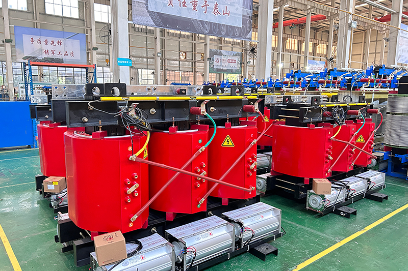
In contrast, dry-type transformers like SCB series have lower thermal tolerance. Their typical short-term overload limit is 1.2× rated current for no more than 1 hour, due to limited heat dissipation capacity.
2. Long-Term Overload
Long-term overload lasts for several hours or even days. In this case, strict temperature rise limits must be observed:
· Oil-immersed transformer: Top oil temperature ≤ 105°C; winding hot-spot temperature ≤ 98°C (IEEE C57.91).
· Dry-type transformer: For F-class insulation, winding temperature rise should not exceed 100K when ambient is 40°C.
Key Limitations of Transformer Overload Capacity
1. Temperature Rise Limits
The heat tolerance of insulation materials directly determines overload limits. For example:
· Oil-immersed transformers generally allow top oil temperature up to 105°C and winding hot-spot temperature up to 140°C under short-term conditions.
· Dry-type transformers follow insulation class rules: 155°C for Class F, 180°C for Class H.
Long-term overload significantly accelerates insulation aging. It’s commonly accepted that every 6–8°C increase in winding temperature cuts transformer lifespan by half.
2. Time Limit for Overload Operation
Overload tolerance depends on both the overload ratio and duration:
· 30% overload: May last 30 minutes to 2 hours, depending on cooling efficiency.
· 50% overload: Typically limited to 10–30 minutes.
· Emergency overload (100% over): Lasts only a few minutes and is typically used during fault backup scenarios.
For cyclic or periodic loads, the overload aging impact must be calculated using thermal aging models, such as those defined in IEEE C57.91.
3. Cooling Method Efficiency
The transformer's ability to handle overloads is tightly linked to its cooling system:
· ONAN (Oil Natural Air Natural): Relies on natural convection, offering limited overload capacity.
· ONAF / OFAF: Forced air or oil cooling can boost overload capacity by 20–30%.
· Dry-type transformers: With forced air cooling (AF mode), overload can reach 150% of rated load in short durations.
4. Design Margin and Load Type
Some transformers are manufactured with a built-in design margin (10–20%), allowing short-time overload operation without damage.
Also, peak loads (like daytime electricity spikes) are less damaging than constant overloads due to lower cumulative thermal stress.
5. Additional Limiting Factors
· Short-circuit strength: Under overload, fault current may exceed the transformer's mechanical strength limits.
· Oil degradation: Overload accelerates insulation oil aging and gas generation. Regular Dissolved Gas Analysis (DGA) is required.
· Protection settings: Overcurrent protection devices (e.g., relays) may trip early, restricting overload performance to prevent equipment damage.
Transformer overload capacity is influenced by a complex interaction of insulation class, temperature limits, cooling method, and design standards. While transformers can tolerate short-term overload under controlled conditions, long-term overload must be managed carefully to avoid insulation breakdown, aging, and reduced service life.
To optimize transformer performance and ensure safety, it's essential to perform thermal simulations, monitor temperature and oil quality, and follow standards such as IEC 60076-7 and IEEE C57.91. When in doubt, consult transformer manufacturers for overload guidelines tailored to specific operating conditions.
1250kVA oil immersed transformer price
1600kVA oil immersed transformer
FR4 Machined Parts
1250kVA oil immersed transformer
Filament Wound Epoxy Tube
- more+releated article
- 2026-02-281250kVA Oil-Immersed Transformer Price and Cos
- 2026-02-27Detailed Explanation of FR4 Machined Parts Mac
- 2026-02-27Custom 1600kVA Oil Immersed Transformer Manufa
- 2026-02-26Precision FR4 Machined Parts for Electrical In
- 2026-02-26High-Quality Industrial 1250kVA Oil-Immersed T
- 2026-02-25Why is Filament Wound Epoxy Tube More Expensiv
- 2026-02-25XUJUE ELECTRICAL Officially Resumes Operations
- 2026-02-25Solar Duty Transformer: Sizing Challenges, Inv
- 2026-02-11Ztelecgroup Annual Gala Successfully Held
- 2026-02-10G10 epoxy board in the insulation parts of ele
- ELECTRICAL INSULATION BOARD MATERIALS
- ELECTRICAL INSULATION MATERIALS
- POWER TRANSFORMER
- ENAMELED WIRE
- SWITCHGEAR


1250kVA oil immersed transformer price
1600kVA oil immersed transformer
FR4 Machined Parts
1250kVA oil immersed transformer
Filament Wound Epoxy Tube
solar duty transformer
G10 epoxy board
G10 Fiber Sheet
G10
G11 epoxy sheet
G11 Fiber Sheet
Laminated wood
electrical laminated wood
Black FR4 Anti-Static Fiberglass Board
FR4 anti-static fiberglass board
Black FR4 Anti-static Board
ddp
DDP diamond dot paper
DDP Diamond Dotted Paper
DDP diamond dotted paper supplier
Electrical Paper Pressboard
3240 fiberglass sheet
FR4
Factory Insulation Paper
FR4 epoxy board