Oil-Immersed Transformer Voltage and Capacity: How to Match Efficiently
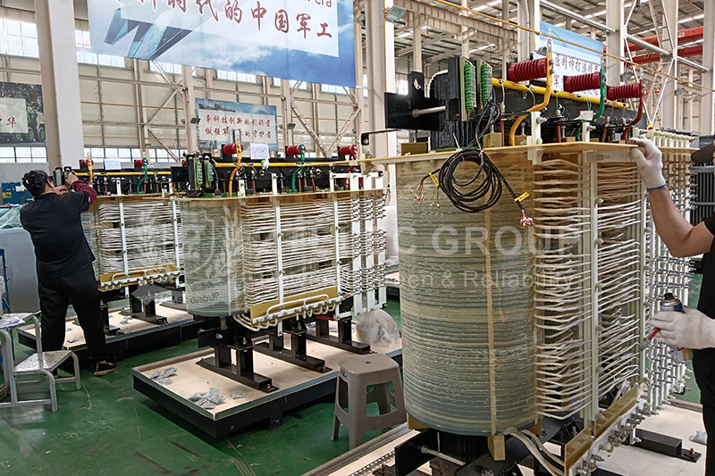
Oil-immersed transformers are the core equipment used for voltage transformation and power distribution in electrical systems. Based on the principle of electromagnetic induction, they adjust voltage levels between transmission and distribution stages. Matching the right voltage and capacity is essential for ensuring system stability, operational safety, and long-term efficiency. This article explains how to properly match voltage levels and capacity for oil-immersed transformers by addressing selection principles, technical parameters, and common pitfalls.
Understanding Voltage Levels
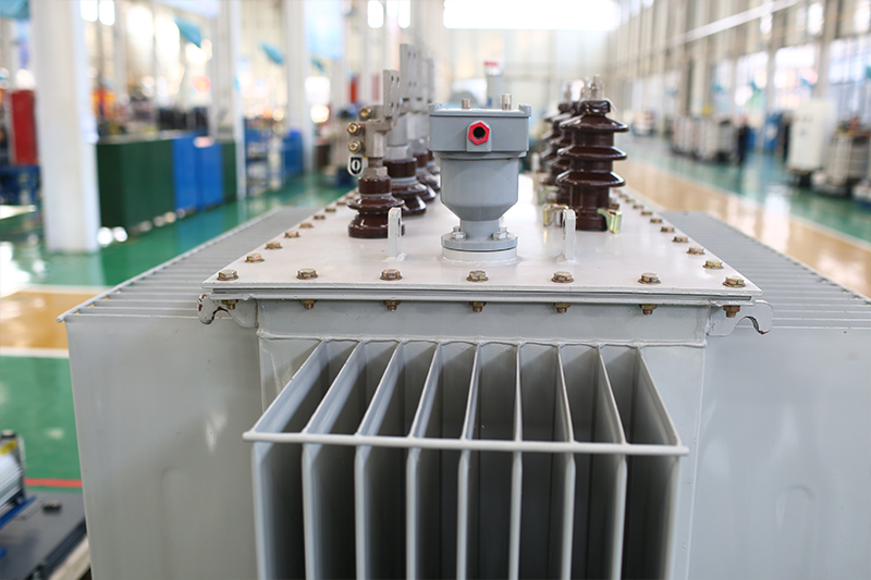
Voltage level matching is the foundation of transformer design and directly impacts compatibility with the grid and downstream loads. Engineers must ensure the transformer’s primary and secondary voltages are aligned with system requirements.
1. Voltage Matching with the Grid
The rated voltage on the high-voltage side (primary) and low-voltage side (secondary) must correspond to the actual voltage levels of the power grid and load devices. Typical voltage configurations include:
10kV/0.4kV: Widely used in industrial and residential distribution networks. The 10kV primary side connects to the utility grid, while the 0.4kV secondary side delivers power to equipment and buildings.
35kV/10kV: Common in regional substations, where 35kV transmission voltage is stepped down to 10kV for local distribution.
2. Tap Changer Adjustment
To accommodate voltage fluctuations (typically within ±5%), oil-immersed transformers are equipped with tap changers on the high-voltage side. Common adjustment ranges are ±5% or ±2×2.5%. By adjusting taps, the number of winding turns changes, ensuring the output voltage remains close to its rated value even when input voltage varies.
Principles for Capacity Selection
Transformer capacity refers to the maximum load it can safely carry, measured in VA or kVA. Proper capacity selection must take into account load behavior, peak conditions, and future expansion.
1. Load Characteristics
Continuous Loads: Choose a transformer with a rated capacity slightly above the long-term maximum load. A typical load rate recommendation is 80%–90%. For example, for a continuous load of 400kVA, a 500kVA transformer offers a safe buffer.
Peak Loads: For applications with short-term load surges (e.g., motor startups), verify the transformer’s overload capacity. Oil-immersed transformers can typically handle 1.5× rated load for 30 minutes. If peak demands exceed this, a higher-rated transformer should be used.
2. Load Types
Resistive Loads (e.g., heaters, lighting): These have a power factor close to 1. Capacity can be selected based directly on total power consumption.
Inductive Loads (e.g., motors, welders): Reactive power must be considered. Use the formula: Apparent Power (kVA) = Active Power (kW) ÷ Power Factor. For instance, a 200kW motor with a power factor of 0.8 requires a transformer of 200 ÷ 0.8 = 250kVA.
3. Allowance for Future Expansion
To support load growth, add a reserve margin of 10%–20% to the calculated capacity. This prevents future overload and avoids the need for premature equipment replacement.
Energy Efficiency and Heat Dissipation
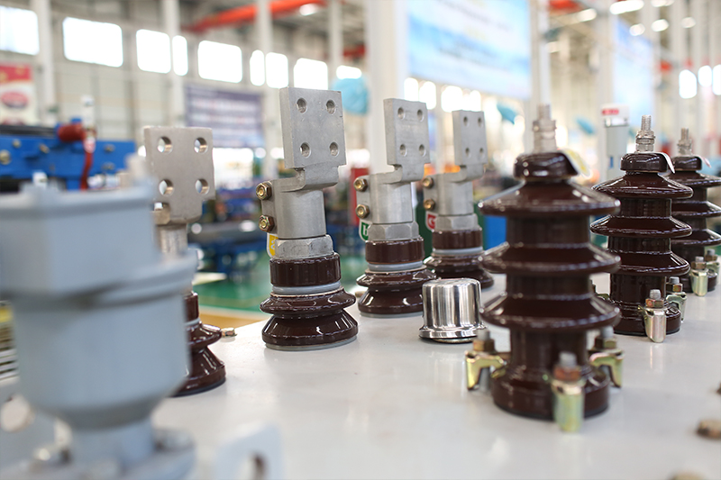
Transformer efficiency and cooling performance directly impact energy costs and equipment lifespan. Engineers should focus on product compliance and cooling configuration.
1. Compliance with Energy Efficiency Standards
Choose energy-efficient models that meet national or regional standards (e.g., China’s GB 20052). Products like the S13 oil-immersed transformer use high-permeability silicon steel and optimized windings to reduce no-load and load losses, making them suitable for continuous operations.
2. Cooling Method Selection
The larger the transformer capacity, the greater the heat output. Choosing the correct cooling method ensures safe thermal management:
ONAN (Oil Natural Air Natural): Uses natural convection of oil and ambient air, suitable for units up to 500kVA.
ONAF (Oil Natural Air Forced): Adds fans for increased airflow and is effective for 1000kVA to 6300kVA transformers.
OFAF (Oil Forced Air Forced): Uses oil pumps and fan-cooled radiators for high-capacity transformers (above 8000kVA), enabling superior heat dissipation and temperature control.
Short-Circuit Verification
Transformers must withstand short-circuit faults. This is achieved by properly selecting the impedance voltage and ensuring compatibility with the protection system.
1. Impedance Voltage Matching
Impedance voltage (typically 4%–10%) affects the magnitude of short-circuit current. For systems with high short-circuit capacity, a transformer with higher impedance (e.g., 10%) helps limit fault currents. For systems with lower fault capacity, a lower impedance (e.g., 4%) reduces voltage drops during operation.
2. Protection Coordination
Ensure the transformer’s short-circuit withstand rating aligns with the breaking capacity of protective devices (e.g., circuit breakers or fuses). This ensures that faults can be safely interrupted before damage occurs.
Common Mistakes and Practical Solutions
Mistake 1: Selecting capacity based only on load power without considering power factor. Consequence: Underestimated demand leads to overheating. Solution: Always calculate apparent power and include safety margins.
Mistake 2: Assuming higher high-voltage ratings are always better. Consequence: May result in excessive short-circuit currents and inflated equipment costs. Solution: Choose voltage levels that match the system’s fault capacity and design specifications.
Mistake 3: Ignoring harmonic distortion from nonlinear loads. Consequence: Overheating, increased noise, reduced transformer life. Solution: Use harmonic filters or select K-rated transformers (K-factor ≥ 13–14) to handle distorted waveforms.
Matching the voltage and capacity of an oil-immersed transformer requires a balance of technical precision and long-term planning. From voltage compatibility to thermal management and fault tolerance, every decision affects the transformer’s performance and reliability. By avoiding common pitfalls and applying proven selection principles, engineers can ensure efficient and safe operation across a wide range of power applications.
- more+releated article
- 2025-12-13How to Select and Use Phenolic Cloth-base Lami
- 2025-12-13How Much Does Bakelite Sheet Cost? 2025 Price
- 2025-12-13Why are most 3240 epoxy boards yellow?
- 2025-12-13What are the Main Applications of FR4 Epoxy Bo
- 2025-12-13Why Does the Price of Insulating Paperboard Va
- 2025-12-13Heat-Resistant DDP Insulation Paper
- 2025-12-13Comparison of Heat-Resistant DDP Insulating Pa
- 2025-12-13G10 and FR4 Epoxy Boards: Commonly Used for Ge
- 2025-12-13The Price of Heat-Resistant DDP Insulation Pap
- 2025-12-13How to Choose Epoxy Laminate Materials for Gen

