In-depth Analysis of Substation Transformers: Functions, Structure, and Working Principles
In modern power systems, substation transformers serve as essential equipment linking power generation, high-voltage transmission, and end-user distribution. They are widely deployed in urban power grids, industrial parks, data centers, renewable energy plants, and large infrastructure projects. Their core responsibilities include voltage transformation, power distribution, electrical isolation, and system stability assurance.
This article provides a comprehensive analysis of substation transformers from three key perspectives: functional roles, structural composition, and fundamental working principles. It is intended to support engineers, procurement specialists, and power industry professionals in understanding transformer performance characteristics and selection criteria.
Core Functions of Substation Transformers
Voltage Conversion
Voltage conversion is the primary function of substation transformers and the foundation of efficient power transmission. At power generation facilities, output voltage levels typically range from 10 kV to 35 kV. Step-up transformers increase these voltages to 110 kV, 220 kV, or even higher to minimize transmission losses over long distances.
Conversely, step-down transformers installed in substations reduce high transmission voltages to medium or low voltage levels such as 35 kV, 10 kV, or 380 V, ensuring compatibility with industrial equipment and end-user electrical systems.
Power Distribution
Substation transformers enable efficient power distribution by allocating electrical energy across multiple outgoing feeders. They support flexible adjustment of power supply capacity and coverage based on real-time load demand, ensuring balanced operation of the grid.
Electrical Isolation
Through magnetic coupling rather than direct electrical connection, substation transformers provide effective electrical isolation between high-voltage and low-voltage systems. This isolation enhances operational safety, reduces fault propagation risk, and improves overall system reliability.
Impedance Matching
By optimizing system impedance, transformers improve transmission efficiency and help limit short-circuit currents. Proper impedance design plays a critical role in protecting downstream equipment and maintaining grid stability during fault conditions.
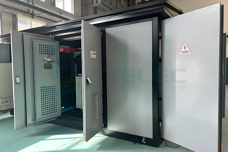
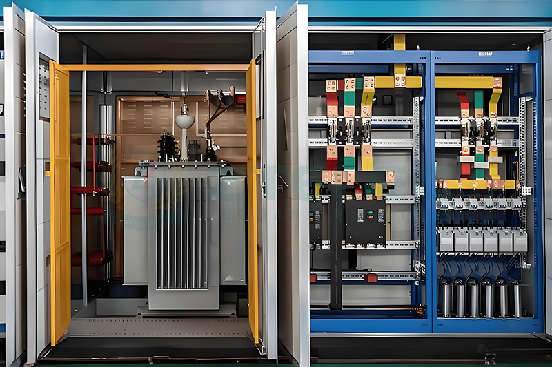
Structural Composition of Substation Transformers
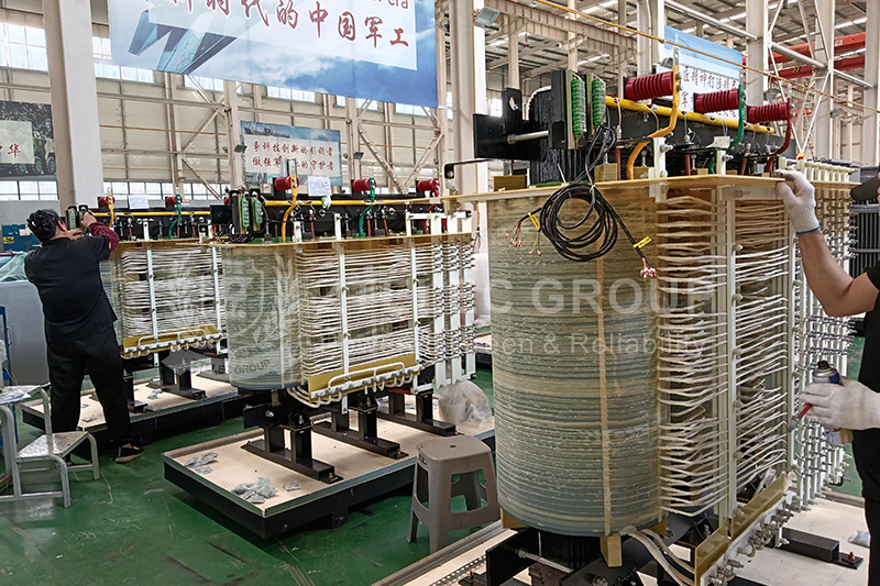
Core Components
The transformer core is constructed from laminated high-permeability silicon steel sheets designed to form a low-loss magnetic circuit. Laminations reduce eddy current losses and improve efficiency. Common core configurations include core-type, shell-type, and three-dimensional core structures.
Transformer windings are divided into high-voltage and low-voltage windings. High-voltage windings typically use thinner conductors with more turns, while low-voltage windings use thicker conductors with fewer turns. Winding materials are primarily electrolytic copper or electrical-grade aluminum, depending on performance and cost requirements.
Insulation systems for windings include paper insulation, enamel coatings, and composite insulation materials, ensuring electrical strength and long-term operational reliability.
Auxiliary Systems
The cooling system is critical for maintaining safe operating temperatures. Common cooling methods include oil-immersed self-cooling (ONAN), oil-immersed air cooling (ONAF), and forced oil circulation air cooling (OFAF). Cooling media may include transformer oil, air, or water depending on transformer capacity and installation conditions.
The insulation system consists of main insulation and longitudinal insulation. Main insulation separates windings from ground and from each other, while longitudinal insulation protects turn-to-turn and layer-to-layer integrity. Materials such as insulating paper, transformer oil, and epoxy resin are widely used.
Protection devices are installed to ensure safe operation and early fault detection. These include gas relays, pressure relief valves, temperature monitoring systems, and oil level indicators.
Voltage regulation is achieved through tap changers, which are classified into off-load tap changers and on-load tap changers (OLTC). These devices allow voltage adjustment to accommodate grid fluctuations and load variations.
The oil tank and related accessories include the main tank, oil conservator, breather or dehumidifier, and high-voltage and low-voltage bushings, all of which contribute to mechanical support and insulation performance.
Working Principles of Substation Transformers
Electromagnetic Induction Principle
Substation transformers operate based on electromagnetic induction. When alternating current flows through the primary winding, it generates an alternating magnetic flux within the iron core. This magnetic flux is transferred through the core and links with the secondary winding, inducing a corresponding voltage.
Voltage Transformation Relationship
The voltage transformation ratio of a transformer is determined by the ratio of turns between the primary and secondary windings. In practice, the voltage ratio closely matches the turns ratio. By carefully designing winding parameters, transformers can efficiently convert between different voltage levels required by the power system.
Energy Transmission Characteristics
Transformers do not generate electrical energy. Their function is to transmit and convert energy through magnetic field coupling rather than direct electrical conduction. This mechanism enables safe, efficient, and flexible power transfer across voltage levels.
Operation and Maintenance Considerations
Normal Operating Conditions
To ensure reliable performance, operating voltage should not exceed 105 percent of the rated value. Load levels must remain within design specifications, and cooling systems should operate normally. Transformer oil quality must comply with relevant industry standards.
Key Maintenance Practices
Routine maintenance includes regular oil sampling for chromatographic analysis and dielectric strength testing, continuous monitoring of winding temperatures, periodic inspection and cleaning of bushings, and scheduled servicing of on-load tap changers. Proper grounding system inspection is also essential.
Common Faults and Troubleshooting
Typical winding faults include inter-turn short circuits and grounding failures. Core-related issues often involve multi-point grounding or localized overheating. Bushing faults may present as flashover, rupture, or oil leakage, while tap changer problems often arise from poor contact or mechanical jamming.
Substation transformers are critical assets in modern power systems, directly influencing grid safety, efficiency, and reliability. As electrical networks evolve toward higher intelligence, sustainability, and integration of renewable energy, transformer technology continues to advance accordingly.
A comprehensive understanding of substation transformer functions, structure, and operating principles provides valuable guidance for equipment selection, operation, maintenance, and long-term system planning.
If you are searching for a reliable and experienced substation transformer manufacturer, please feel free to contact us for technical support and customized solutions.
- more+releated article
- 2026-01-08Epoxy Pre-impregnated DMD vs. DMD: Key Differe
- 2026-01-08Why Oil Type Transformers Are Still a Core Com
- 2026-01-08Insulation Paper Production Cost and Profit An
- 2026-01-08How do the processing characteristics of DMD p
- 2026-01-08150KVA Three-Phase Dry-Type Isolation Transfor
- 2026-01-08Specific Applications of Glass Fiber Wound Tub
- 2026-01-08Why Data Centers Choose Three-Phase Isolation
- 2026-01-08G10 Glass Fiber Filament Winding Tube Standard
- 2026-01-08European Prefabricated Substation Design: Inte
- 2026-01-08Application of SMC Insulation Boards in Switch
- ELECTRICAL INSULATION BOARD MATERIALS
- ELECTRICAL INSULATION MATERIALS
- POWER TRANSFORMER
- ENAMELED WIRE
- SWITCHGEAR

- dmdinsulation paperDMD PrepregThree-Phase Dry-Type Isolation TransformerGlass Fiber Wound TubeG10 Glass Fiber Filament Winding TubeSMC Insulation BoardsInsulation Paper NMNvoltage conversion transformertransformer working principlePower transformertransformer structuresubstation transformertransformer oil conservatorpower transformer accessoriesoil conservator tankOil immersed transformerChina transformer manufacturersChinese-made power transformersglobal power transformersenergy efficiency transformerspower transformer selectiontransformer procurement mistakestransformer overloadtransformer overheating